Hello and welcome back👋
We’ve just wrapped up the first week of our second sprint, with one more week still ahead. In this post, we’re excited to share an update on what our team has been working on so far and give you an overview of our current progress.
Fredrik:
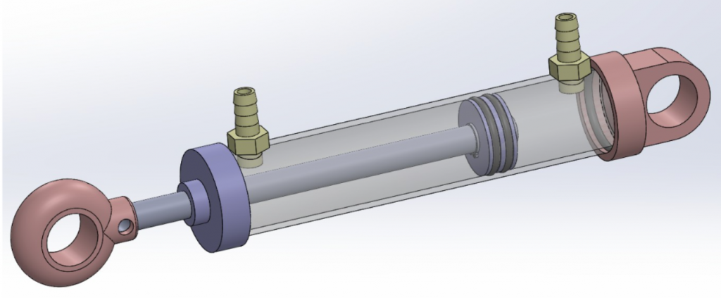
This week we started on sprint 2, which for the mechanical side mostly focuses on developing a proof of concept hydraulic system. Many parts are needed for this, so this week I started development on the hydraulic cylinder, which will be mounted on the arm to move its joints. Erling and I decided to make a double acting hydraulic cylinder, as that would give us precise and controlled movement. It consists of two ports for pressurized water to flow through, the piston between them, and a shaft spanning from the piston to outside the cylinder.
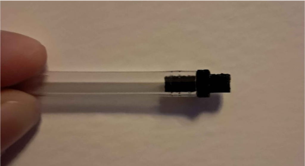
It was challenging to be able to make this with the limited resources I have access to. I will use PVC pipes with diameter 16mm from Clas Ohlson for the cylinder itself, seeing as it is easily accessible and cheap. For the two ports I needed some sort of hose barb to connect the tube to the cylinder. I decided to attempt 3d-printing this, despite its small size. I used PETG, as it’s stronger and has lower moisture absorption than PLA. I also choose my print orientation carefully, to bring strength to the smallest cross section. The finished print seemed to be strong enough, and fit well with the tube we are using. The rest of the assembly will likely be 3d-printed, and utilizing o-rings borrowed from Erling. I have designed an early iteration of the cylinder in solidworks, seen in the picture below.
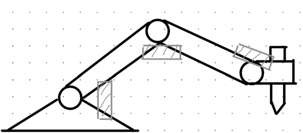
Defining the layout of the arm is a big step towards realizing our project. For us, this was important to define early, to be able to simulate the inverse kinematics.
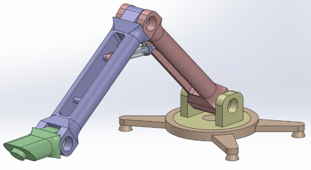
I chose a design requiring four cylinders, shown in the first picture below. I choose this because the more cylinders we have, the more complex inverse kinematics, and the more points of failure we have. Seeing as the robot will primarily move in 2d, adding more than four cylinders seems unnecessary. I made an early 3d-model of the arm, only for visualizing how it would function and move, seen in the second picture below
Lisa:
This week I worked on a proof of concept (PoC) transmission between the Raspberry Pi (RPi) and Arduino. The goal was to test whether it makes sense to split the system into two parts:
- The Raspberry Pi runs the user interface (website) and handles image processing and planning.
- The Arduino acts as a small real-time system, dedicated to controlling kinematics and smooth motor movements.
If this setup works well, we get the best of both worlds. If not, we may drop the Arduino and let the Raspberry Pi handle everything alone.
How can two devices communicate?
To make the Raspberry Pi and Arduino communicate, I needed to look at different methods for data transmission:
- USB Serial: Use a regular USB cable. Easy to set up and reliable.
- UART: A more direct connection through pins. Potentially faster, but requires level shifting for safe voltage levels.
- I²C/SPI: Common in electronics, but not really necessary for our current setup.
All of these approaches are possible for our system. For this proof-of-concept, I decided to start with USB Serial since it provides the fastest way to get a working test up and running.
What kind of data should be sent?
I explored two approaches for sending instructions:
- Streaming mode: The Raspberry Pi continuously sends new positions, almost like live commentary (“move here, then here…”).
- Batch mode: The Raspberry Pi sends a full list of waypoints in advance, and the Arduino executes them locally with correct timing.
Both approaches could work for our system, and by the end of this sprint I should have a clearer idea of which one makes the most sense to use.
What I found so far
Based from my research so far, here’s what I’ve found out:
- The data volume is very small, which means both USB and UART should easily handle the transmission.
- Typical latency for these methods is only a few milliseconds, which is good enough for our use case.
With simple error checking, such as a Cyclic Redundancy Check (CRC), the system can detect if a message was corrupted during transmission.
Why this matters
The big question is whether it is worth having two devices. The Arduino could give smoother and safer motor control because it only focuses on timing and movement. But if the Raspberry Pi can handle this well enough on its own, it may not make sense to maintain two systems.
That said, keeping both boards does create a clear separation of tasks: the Raspberry Pi can handle planning and interfaces, while the Arduino runs the real-time control. This makes it likely worth continuing with both.
For now, starting with USB Serial seemed like the easiest way to get the concept up and running. Later, as we focus more on stability and real-time performance, it will also be valuable to compare with UART, which could give us lower latency and better control over timing.
Syver:
This week I mainly worked on getting the webpage and Python backend to run on a Raspberry Pi.
The first part was to reset and boot up the Pi. It had been shelved for quite a bit, so I didn’t really know what to expect in terms of performance. We didn’t really have the budget to buy a new one, which is why we settled on this older version I had lying around for now. The goal is to allow users to connect to a “HYDRAWLICS” WLAN hosted by the RPi, and be met with the website shown in our last blog post.
The Pi is a Raspberry Pi 3 Model A+, featuring a modest I/O, but it importantly has onboard Wi-Fi which will be used to serve the website. Installing OS and such went smoothly. I went for Raspbian, based on Debian bookworm, giving wide support for various Debian tools as well as wide support online for its default configuration. It is also quite lightweight. Having a bit more capable SoC like the RPi 3 for GUI and a separate Arduino for real time kinematics control, is what we are aiming for. The pathways calculated by Emory’s algorithm will be transferred to the Arduino using the communication method Lisa has researched.
Having the OS set up and updated, I started writing scripts and routines for switching between access-point and client Wi-Fi mode. I tested being able to access the Pi through SSH in both modes, then moved on to installing our project there.
Installing our project was quite easy, due to the newest Python being available and its support of the latest Bun runtime. Having everything up and running allowed me to test the performance of the image processing. I haven’t gotten to doing formal timed tests, but I estimate it to take about 20s processing an image as of now. Quite a bit slower than on a computer, which takes <1s. In addition to this, general usage and management of the Pi was relatively slow. We will monitor the performance as we evolve the algorithm and evaluate if we need to consider upgrading this to a faster SoC in the future.
With this, the GUI is accessible from any device connected to the Wi-Fi! What remains is mainly to set up nodogsplash or a similar tool to serve as a captive portal for GUI access, and some more performance testing, and optimize if necessary. I’ll focus on that towards the end of our sprint.
Emory:
Since I had already used OpenCV (Open Source Computer Vision) which is a computer vision library for performing operations on pictures and videos for the previous part of the code, it made sense to me to check if there was an implementation inside that I could use to continue the code, finding the contours of the image and converting them into a vector that the machine can draw from.

The picture above is from what I did the previous week, so it’s easier to see what has been done for this week in continuing the code to make a raster image into vector format.
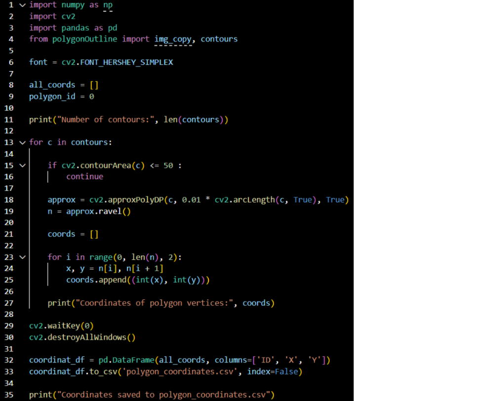
Started with using the canny edge algorithm from last week and finding the contours from that. The first code snippet takes the processed image from the Canny edge and finds the contours from that, as shown below.

After that, the second code snippet uses the contours to detect polygons in the image. It calculates the area and, based on the precision, creates a polygon outline of the contours. It classifies the shapes found and draws lines between the points.

The third code snippet utilizes the polygon outlines to determine the coordinates of their edges. It loops through the contour and ignores areas under 50 to reduce noise, then simplifies the contour. Afterwards, it collects the polygon coordinates in a loop to make sure we get all of them.
All of the coordinates are converted into a pandas DataFrame and then saved inside an Excel file to be able to use later.
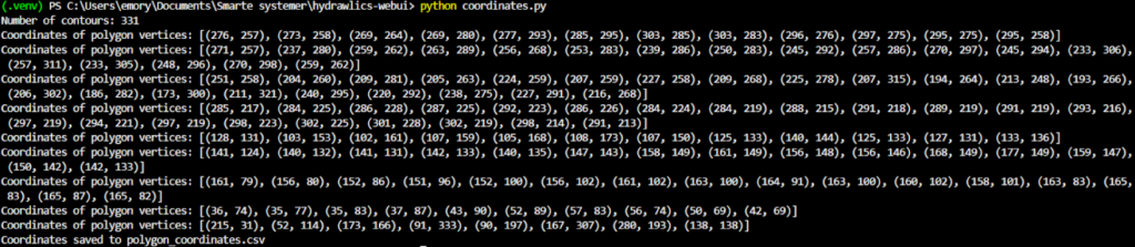
A small snippet on how the CSV file looks:
So far, the coordinates look like this. So, a further fix would be to check that the coordinates would work for the robot to draw from. Did do a quick check to see if ChatGPT could draw it, and this is what it made.
So grouping the coordinates with the polygon they belong to would help in getting the output we want from the coordinates, so that they can be drawn correctly.
Erling:
This week i have been focused on determining how we can implement a realistic hydraulic system into our project. I have been looking into valve mechanisms and attempting to figure out what is really needed in terms of valves. I did this on paper primarily for concept generation.
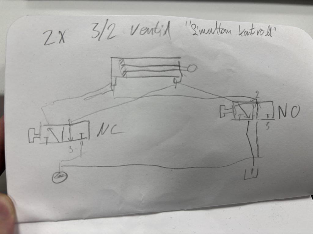
To verify my thinking, i have used Festo Fluidsim, a Pneumatics and hydraulics simulation software from FESTO, a leading actor in this space.
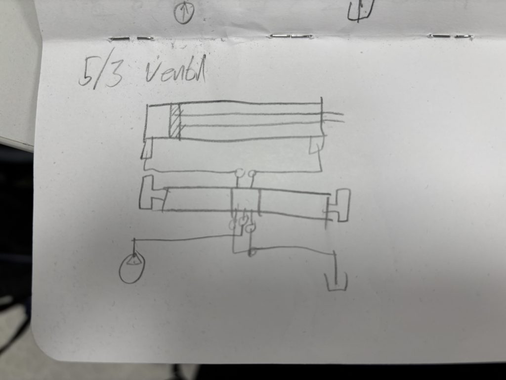
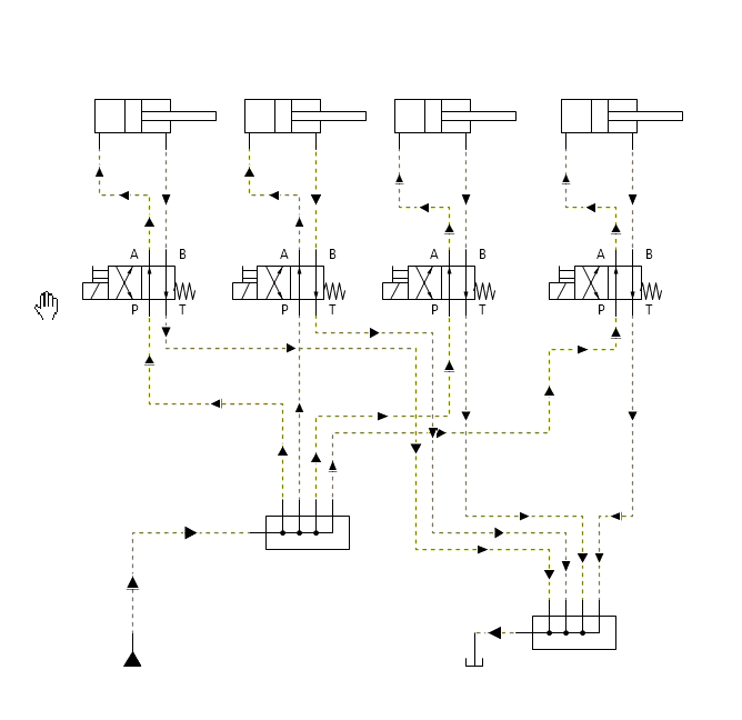
From left to right; a system with a 5/3 pneumatic valve that might work, a GIF of a system with 3/2 valves that wont work, a system with separate activation of a 5/2 valve that is also not suitable.
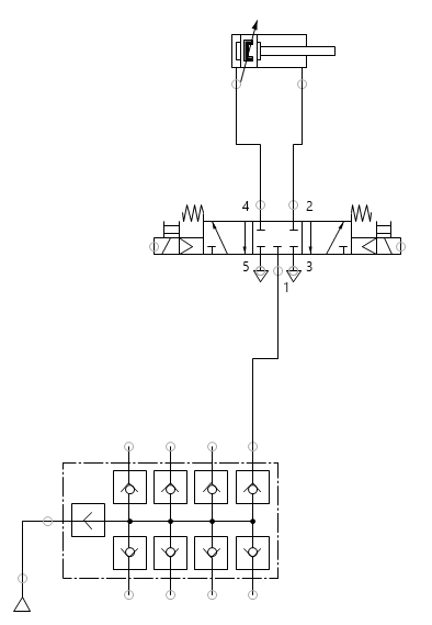
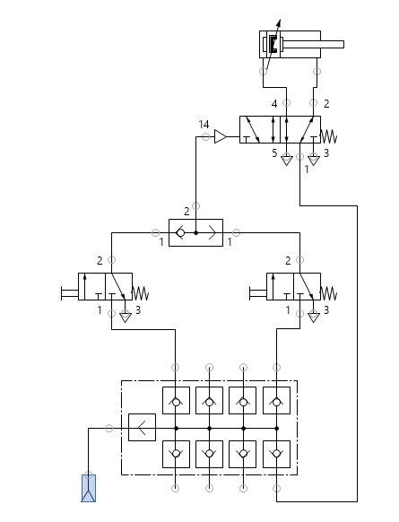
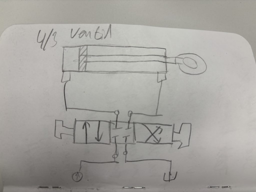
Under is a video of a system that uses 4/3 valves to control the cylinders. This would work, but is expensive to aquire.
In order for our robot arm to be as stable and predictable as we need, it needs to have active position hold on the cylinders. I have found two main ways this is achievable: using hydraulic 4/3 valves with a shutoff position, or using pneumatic 5/3 valves with shutoff position and combining the to exhaust ports to one and leading to back to the tank.
For our project, using pneumatic valves with water should not be a problem, because of our expected system life time. Corrosion in the valves will not be an issue.
This is a challenge under our budget constraints. I have already contributed 120 + 22 + 37 NOK for the water pump, syringes, and PVC tubing for the project. Purchasing solenoid operated valves may prove to be too expensive for this course.
Another option might be to look into single acting cylinders, and performing tests on position holding power to determine usability of such a solution.
Our sprint 2 lasts another week, so we will continue looking into the possibilities a bit more.
That’s all for now, see you next week!