Henning
For last week I was mainly focusing on making a third-party GUI for our project. As we were missing certain parts for our car and others in the group has been more focused on the base car code (to make it drive, turn and have the sensors function). I on the other hand focused more on an end goal that we might apply to our car. The GUI I have made so far is just a prototype for testing as I’m currently learning a new program called QT.
Here is an example:
This is the GUI. It is plain and simple, and I will quickly describe what the thought process is here:
- The “Connect to AI” button should connect us up to an AI through either an API or locally on the computer
- I have been researching around DinoV3 which is META`s AI that specializes in satellite pictures. (Might implement this)
- The “Show data” button should open a dashboard that will track the data from each of our sensors on the car. That would be speed, direction the car is driving and pictures from the camera itself.
As for now in my test GUI, I have only been able to connect these buttons to pictures so far, but upcoming week I will be focusing more on reaching the goals of what I have listed above.
The code so far using QT:
As I am now getting more used to this program and how the syntax and code is written, the progress towards upcoming week should help me provide with a deeper code. Look forward to next week`s progress!
Wang
This week I`ve been looking more into the micro: bit. Now i got vscode IDE to code with there i us Arduino language. Now i know where det pins to the light are i can display something and i know how the buttons works. I have also looked at DC-motor since i think those are the motors that are connected to the omni wheel. So a DC-motor has 2 controller pins per motor. So the code most go something like this. Since we want to be able to control one wheel at a time, we need to set up a function for each wheel and each wheel needs to have two functions attached to it, one that goes forward and one that goes backward. So on Monday if the code that I have created here is set up correctly we can get it moving forward. I have looked at some code where they code in Arduino and used omni wheels to see how it can be dune.
📋 Main Tasks I have looked inn to
1. Understanding how Micro:bit works
- Model: Working with V2 model
- IDE: Using VS Code with PlatformIO extension
- Tools: Serial monitor extension for debugging
2. LED control (5×5 light matrix)
- Structure: 25 LED diodes in 5×5 grid (numbered 0-4)
- Column controllers: Pin 4, 7, 3, 6, 10
- Row controllers: Pin 25, 24, 23, 22, 21
- Examples:
- Simple blinking at position (4,4)
- Heart pattern with multiplexing
3. Motor control for wheel movement
- Movement direction:
- Forward: Left wheel clockwise, right wheel counterclockwise
- Backward: Opposite rotation
- DC motor control:
- 2 control pins per motor (often red/black)
- One pin HIGH, one pin LOW determines rotation direction
- Implementation: Functions for forward, backward and stop for both motors
4. Sensor integration
Under development
🔧 Technical Details
Pinout configuration for LED matrix:
- Columns (x): 4, 7, 3, 6, 10
- Rows (y): 21, 22, 23, 24, 25
Motor pins example:
- Motor 1: Pin 2, 3
- Motor 2: Pin 4, 5
Zardasht
My Week with Raspberry Pi 4
Day 1:
I had to switch from a Raspberry Pi 5 to a Raspberry Pi 4 in order to connect the screen, both physically and through software. I prepared the Raspberry Pi 4, downloaded images and the operating system, and got everything ready. With the help of YouTube videos, everything went according to plan. It took me about two hours to download the files and get familiar with the system.
Day 2:
Next, I tried to connect and test the camera on the Raspberry Pi. I had to update the system and install some additional services and libraries. Everything seemed fine, but there was still no sign that the camera was working. I even tried asking an AI for instructions, but nothing helped. Finally, I used a command (vcgencmd get_camera) to check if the camera was connected. The output showed the exact opposite of what I wanted (supported=1 detected=0), indicating that there was a hardware problem. This was very challenging, and I ended up spending more than five hours troubleshooting.
Øivind
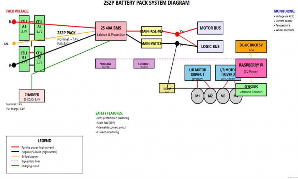
This week have I been researching BMS for the the 18650 batterys intended to power our car. I have a rough sketch for the powersupply –> BMS –>Motor bus and power supply –> BMS –> (maybe SMPS and LDO) –> logic bus for sensors, actuators. I will today, discuss within the group what we will use as sensors for the wheel motion, and will propose Hall sensors to log magnet movement mounted to the wheels. How this shall be implemented is yet to be determined, but I have some ideas. Maybe some rings with the magnets mounted in 2pi/8 (or more) symmetrical spaced. I will today ask for a couple of capacitors, batteries, TVS Diode if needed, thermistor, fuses (maybe polyfuse) and ask for advice for other sensors like current sensor, balancelead and connectors for the powersupply, and if we shall reevaluate the motor drivers we formerly have been advised, since current research deem them ineffective regarding heat and performance. Under I have created a rough sketch for parts of the system I have designed so far.
Oskaras
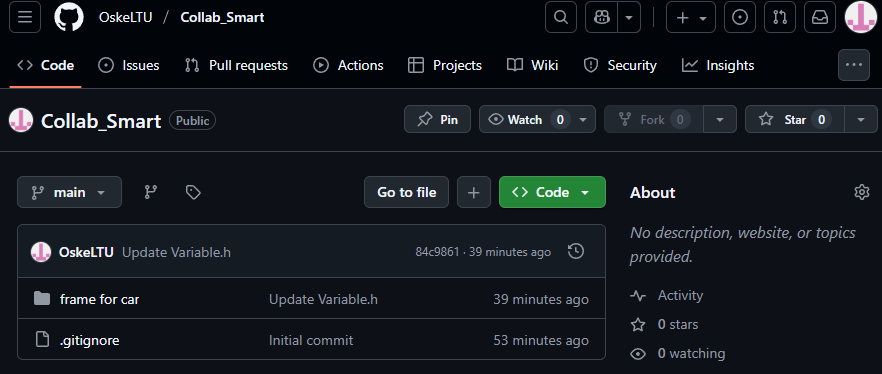
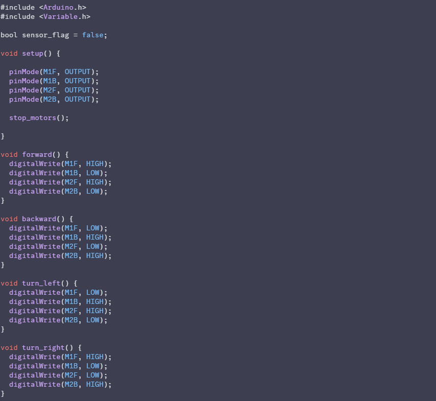
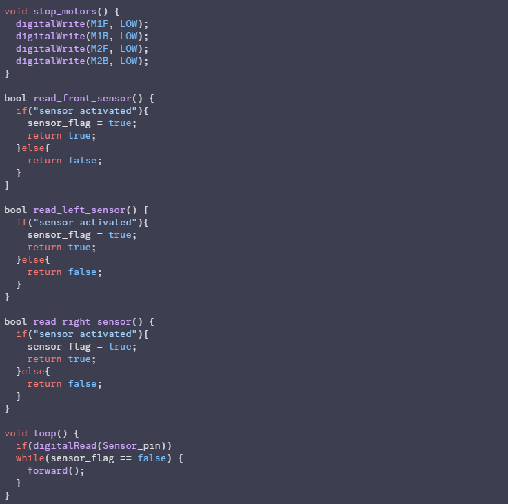
I made a template for the functions for Arduino type code, and setup a github where we can share all our code to cooperate better.
Block of code for functioning the car:
Github: