Hello and welcome back!👋
In last week’s post, we defined our Minimum Viable Product (MVP) and divided the main components into individual responsibilities. This week we have each been working on our parts to bring the MVP to life.
As a reminder, the tasks were distributed as follows:
- Fredrik – Build the actuator system and prototype end effector
- Erling – Design a simple joint mechanism using syringe hydraulics
- Emory – Research and develop a proof-of-concept image edge detection algorithm in Python
- Lisa – Source parts and code the C++ Arduino firmware to demonstrate the motion of the hydraulic arm
- Syver – Implement a baseline Python Flask webserver for collecting and serving user content, serving as the system interface
In this post, we’ll share our individual progress and results so far!
Fredrik
This week I was responsible for the hydraulic actuator system. In other words, I need to push the syringe with the use of an electrical actuator. For this early development phase, I based the design on the components we had easily available, being mainly servo and stepper motor. The stepper motor can exert more power, but the servo has positional awareness. This positional awareness can come in handy for repeatable testing, so we went forward with the servo.
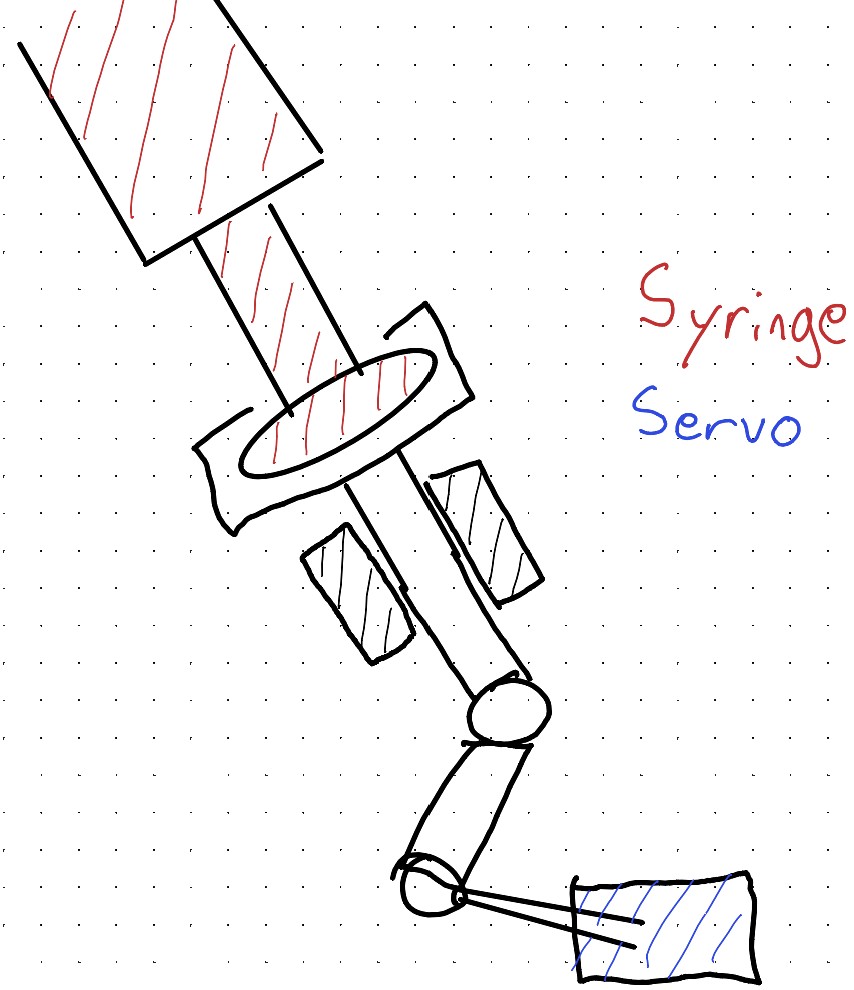
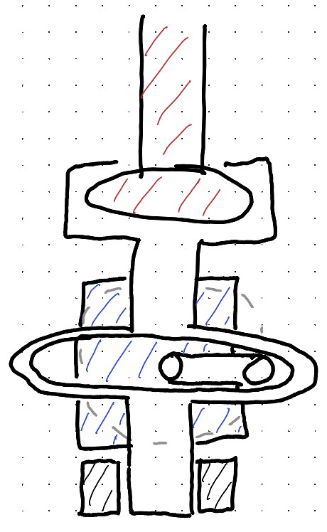
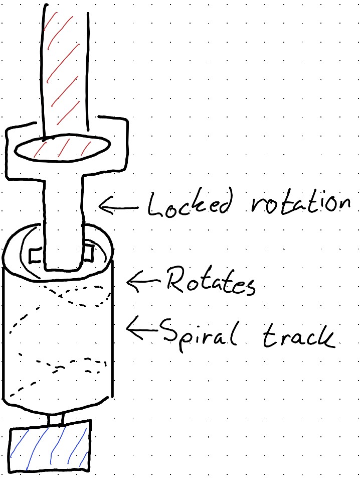
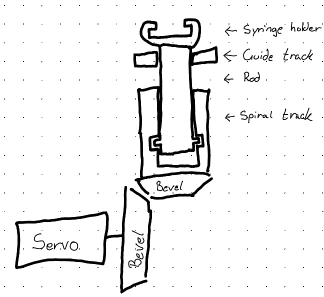
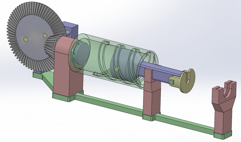
The system needed to convert rotational motion from the servo to linear motion. I brainstormed some concepts of systems that could accomplish this, shown in the images below. I landed on the last of these concepts. This is mainly because the rotational and linear motion is proportional, eliminating the need for solving this in software. Another benefit of this concept is its thin design, with everything being in one line. This would make it easy to stack the system for more syringes.
The sg90 servo can rotate approximately 180 degrees, and the syringe needs to be pushed 66.5mm. I used bevel gears to allow for more rotation in the system per degree from the servo, thereby reducing the linear transmission per degree.
Every part of the system is 3D-printed on my 3D-printer, with the exception of the servo and the syringe. When designing and testing, I quickly understood that friction would become an obstacle. Therefor I played around with different 3D-printing materials, mainly PLA and PETG, and figured out that a PLA surface to a PETG surface had low amounts of friction. Many of the parts in the system is therefor printed with this in mind, trying to alternate between the two.
The finished system is shown in the images below. The system ended up successfully converting rotational motion from the servo into linear motion, with low friction and high precision. Although when attaching the syringe, the force exerted by the system fell short of the required amount, meaning that the syringe was not pushed and pulled in a way that would work in our project. This is shown in the video below. The system did however serve as an excellent proof of concept, and could be further developed into a fully working force transmission system. If I were to work on this concept moving forward, I would look for ways to reduce friction even more, switch to a stepper motor instead of the servo, and consider switching to a rack and pinion system.

Lisa
I’ve been working on my part for the MVP, which was to source the parts and to code the Arduino firmware that will demonstrate the motion of the hydraulic arm.
As a first step, I set up a servo motor that moves along a single axis using the Arduino IDE and electronic components. The Servo will eventually receive instructions from the system to control the arm’s drawing motion. Since we haven’t reached that point yet, I replaced the instruction input with a potentiometer.
This allowed me to manually control the servo, and I was pleasantly surprised by how responsive and well synchronized it was. The servo reacted instantly and smoothly to adjustments on the potentiometer, making it a solid starting point for further testing and development.
On top of this, I have also taken care of maintaining our Notion workspace. I not only make sure that all databases stay updated and synced so the group always has a clear and shared overview of tasks and progress, but I’ve also spent time finalizing the overall structure. This way, the workspace is easier to navigate and provides a solid foundation for us to continue organizing our work efficiently.
Syver
This week, I have focused on setting up a web-based front-end, as well as a boilerplate Python back-end in which the image edge detection code will live. Using a web-based front-end solution allows us to host the website locally, allowing people wanting to use the machine to join a local Wi-Fi and open the website on their personal device. Therefore, making it accessible and user-friendly for all was a big part of designing this GUI.
For the front-end I have decided to use Vue and TypeScript, due to previous experience with this stack. I chose to use Vite as a build tool for now, providing a live development environment, but there is nothing stopping us from building into HTML/CSS/JS and letting the Python back-end host it for us in the future.
Before implementing the GUI, I laid out the general design and components, which are divided into roughly three main parts: top part with logo and status indicator, main large container where the processed image will be previewed, and the bottom container containing the controls and preferences. I focused mainly on simplicity and expandability, making way for new elements (user preferences and such) to be implemented in the future.
The group decided that it would be best to implement the back-end with Python, due to the vast amount of existing resources available. Continuing this line of thought, I chose to go with Flask as the back-end framework. Its clear and simple structure makes it easy to integrate Python libraries being developed in parallel. There are other alternatives like Django or FastAPI, but both are generally tailored to larger projects or heavier workloads.
The endpoints implemented as of now are:
- ‘/ping’ for testing
- ‘/config’ for information about current back-end configuration, like supported file types
- ‘/upload’ to provide input image and receive back the job ID, start processing job
- ‘/jobs/[ID]/status’ for how far the processing is along
- ‘/jobs/[ID]/download’ to get final image
In summary, the web app can now connect to the back-end, display the connection status, and exchange images with the back-end. Here is a quick demo of the front-end web app sending an image to the back-end, and getting back a test image.
Emory
This week, I developed a proof-of-concept for an edge detection algorithm in Python. To achieve this, I began by researching various methods for detecting the edges of an image.
The one method I thought looked most promising was the canny edge detection algorithm. Cause it’s known for a low error rate and is good at localizing edge points. It uses 4 steps in detecting the edges.
- Noise reduction
- Gradient calculation
- Non-maximum suppression
- Double thresholding
Under you can see the implementation of the canny edge detector algorithm.
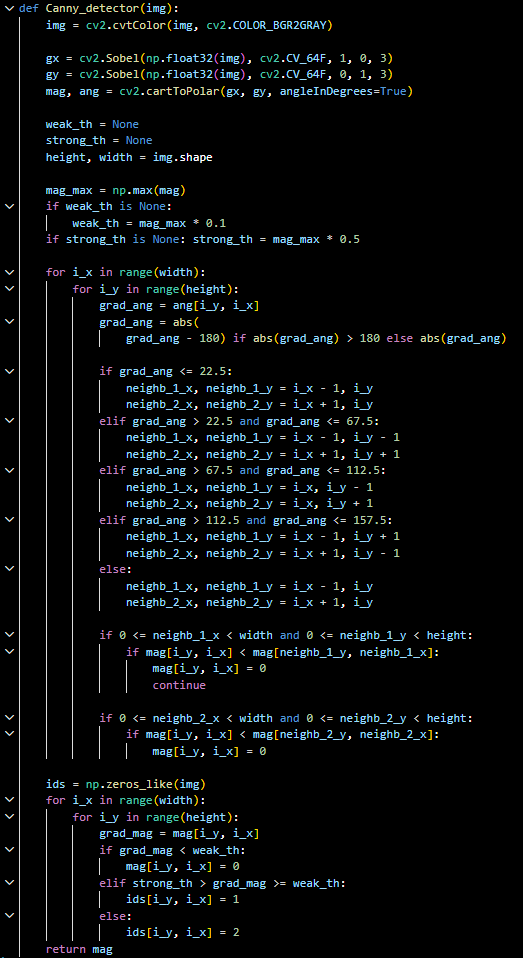
The algorithm has different stages for what it does to turn the original image into a black image with only the edges showing:
- Turns the original image into grayscale.
- Compute gradients using x and y directions
- Calculating the magnitude and angle using the x and y directions
- Setting up thresholds for weak and strong edges based on the maximum gradient
- Checks if there is a local maximum in the direction of the gradient. If not, sets the magnitude to 0
- Classifies pixels as strong edges, weak edges, or non-edges
- Then returns the edge map it has created
The rest of the code consists of finding an image I have in a folder on my pc, starting with making the image into grayscale using cv2, which is from OpenCV, then putting that into the canny edge detector. It prints out the before and after image into a graph so you can see the difference. Like the image below.
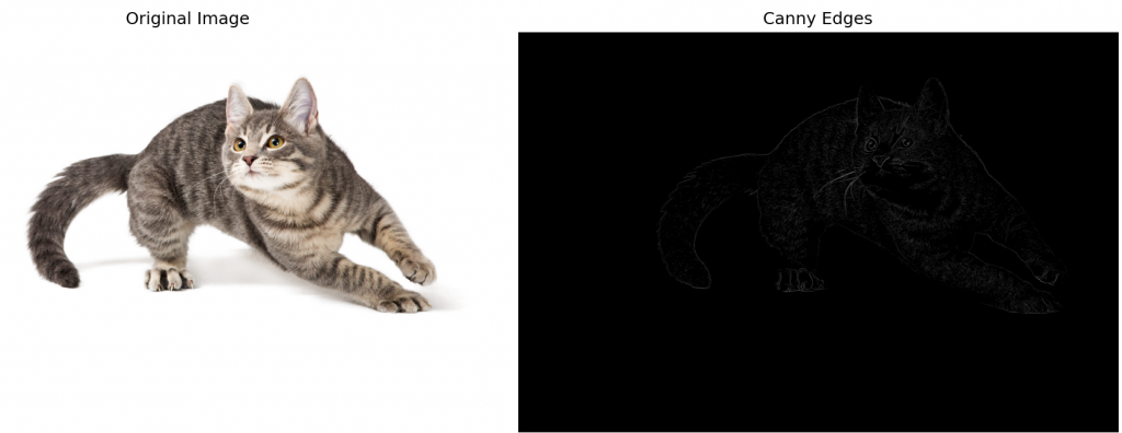
This algorithm gives a good starting point for further development to be able to make an algorithm for plotting the edges into a vector format.
Erling
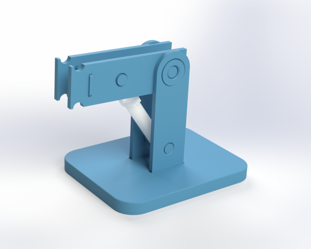
This week i have made the arm structure of the MVP unit. This was designed in Solidworks and printed in PLA on my personal 3D-printer.
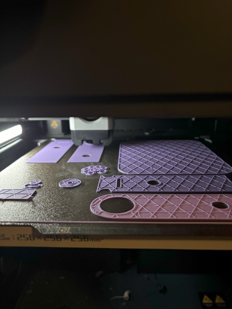
After testfitting my parts i realized i needed to make some modifications in order for the component to fit together properly. The final shape of it looks like this:
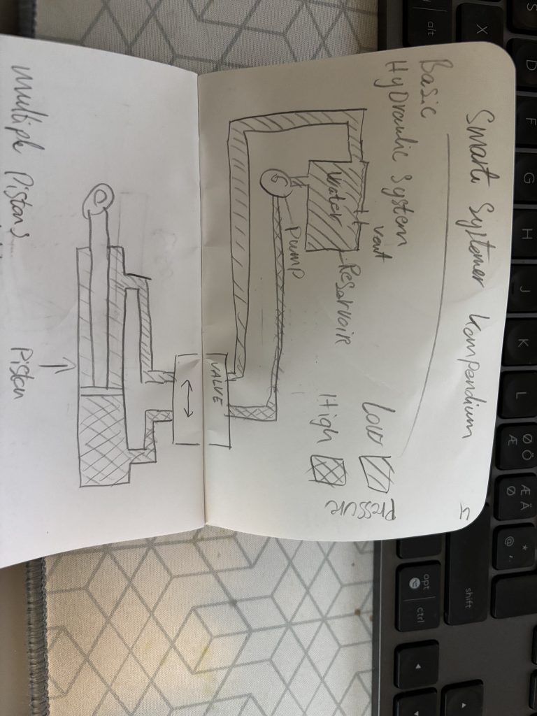
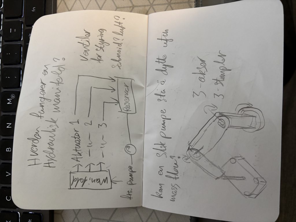
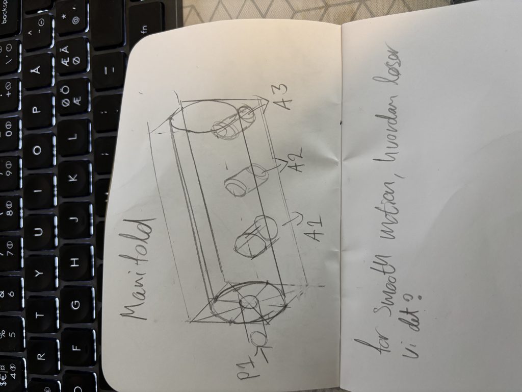
I have done some research and preparation on basic hydraulic systems and hand drawn some simple ideas on possible ways to actuate the syringes in order to move the axes.
I purchased 2 large and 2 small syringes in order to model the arm properly.
In order to make a hydraulic system the way I envision it, we need a water pump. So i bought one on Temu that has 6 l/m volumetric flow and a working pressure of 9 Bar (0.9Mpa). Using Force = Pressure * Area, this means our large syringes may be able to lift a weight of 11Kg.
After modeling in Solidworks i put together an assembly to visualize the movement.
MVP Results
After working individually on our tasks, we are starting to see the MVP take shape. Both the digital and physical parts of the project are coming together, and this week we’ve been able to test and visualize some of the progress!
Digital – GUI and Image Processing
We have combined the GUI with the image processing prototype, giving us a first look at how the system might function when it’s all connected. The code base is growing quickly already – check it out on GitHub!
Physical – First Motion Tests
On the hardware side, we’ve successfully demonstrated motion with the servo-driven hydraulic setup. This is the first step towards the robotic arm being able to follow drawing instructions.
That’s all for now, see you next week!