Bram van den Nieuwendijk
In week 3 I had a tour of the components and machinery we can use at the university. Besides this I had a brainstorm meeting together with Rick and Jonas to develop a concept of the car. This meeting was successful as we now know what the concept is roughly going to be. The next step is to make a 3D drawing of this concept.
| Requirements (mechanical) |
| Robot must have a camera that can rotate over the x-axis |
| Robot must have a spraying nozzle that can rotate on the x+y-axis |
| Robot must be able to rotate on the spot |
| Robot must be able to spray a liquid (H2O) |
| Robot must have speed control |
| Robot must be able to store a liquid (H2O) |
Rick Embregts
To get a better idea of the system and to make sure nothing is forgotten this overview was created of the entire system. This overview is not leading in the sence that the design or components can be changed later. There is also a table to better discribe the function and components used in the design. When more components are defined there will be a more accurate and more specific schematic made. Next week there will be more tasks and deadlines discribed
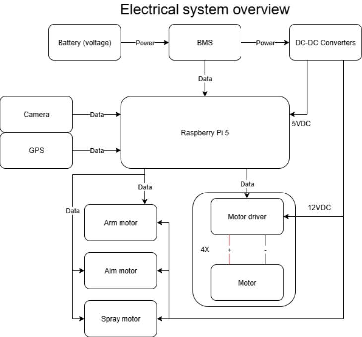
| Discription | Function | Component |
| Drive motors | Motor driving the wheels | Motor/gearbox combo () |
| Arm motor | Motor turning the camera arm | Servo Motor, Stepper motor |
| Aim motor | Motor controlling the vertical momevement of the sprayer | Servo motor (Low power) |
| Spray motor | Air compressor motor to spray liquid | Air compressor/motor combo |
| Motor controller (for drive motors) | Aplies voltage and current to the motor in the right polarity | Unknown |
| Vehicle controller | Micro processor to control the movement of the vehicle | Raspberry Pi 5 |
| GPS module | Device to Identify the position of the vehicle | Ask team members |
| Power supply | Provides power for the systems | 1st generation will be just a power supply. |
| Battery | Stores the energy to move the robot | Unknown |
| BMS | Makes sure the energy is stored in a safe manner | Unknown |
| Converters (DC/DC, 12V, 5V,.3.3V) | Provides correct voltages for the system to opperate | DC-DC Converter |
| Gyroscope | Provides the orientation of the vehicle | Swift Piksi v2.3.1 |
Darkio Luft
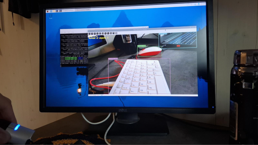
To start the setup and make some tests, I borrowed a Raspberry Pi 400 and a screen.
After setting up the Raspberry Pi OS, I began importing the YOLOv11n object detection model to see if the Raspberry Pi could handle image detection. It worked, but at a relatively low FPS of around 2.15. I’ll try importing a lighter version of YOLO to see if it makes a noticeable difference in the FPS.
Åsmund Thygesen
This week I was supposed to familiarize myself with the raspberry pi, which I have never really used before, and start work on the motion control system.
To start with I needed to install the OS on the raspberry, which was done easily with the raspberry pi imager software. It automatically set up and installed raspberry os on a microSD card. I went with the x64 raspberry pi OS, which is the recommended version and probably a good starting point. It shouldn’t be a problem to change it later if that is needed.
Next up I started thonny, the python IDE the raspberry OS comes with, did an obligatory “Hello world” and started looking at controlling the GPIO pins of the raspberry pi.
The “gpiozero” library makes this really easy and it has a lot of pre-made classes for different functionality. As a test I wrote a simple blinking LED program, I did it first with the LED class, then the PWMOutputDevice class. It’s very simple, but necessary for me to better imagine how I’m going to write the motor control system.
Doing this made me realize I should have a setup where I can write code on my normal desktop PC and just run it on the raspberry. To achieve this I created a github organization for the group and a repo under the organization for the motor control system. This I made public so I can easily access it from the raspberry pi.
For the sake of these blogs and getting proper screenshots from the raspberry in a streamlined manner I also set up a private repo for documentation/blog. To access and push to this from the raspberry pi I generated a fine-grained access token in github that is configured to give access to the documentation repo. I also wrote a bash script to add, commit and push in one go just to make it more convenient. This took longer than it should have, just cause I needed to brush up on my linux skills, it’s been a while since I used it a lot.
With that I can now transfer screenshots and other files from the raspberry pi to my PC with one command via github, which is slightly more convenient than a thumbdrive. In hindsight it seems a bit overkill for simple file transfer, but in the moment, I had the thought and got a bit carried away.
Sulaf
Overview
The goal during this week was to look into Rasberry Pi, familiarize myself with it, download it and navigate through it to get a comprehension of how the basics work. In addition to that, I continued looking at the navigational system, which after discussing with our supervisor, he sprung a new and welcome surprise at us of using a RTK GPS instead. This kind of GPS was unfamiliar to me, having never worked with something of that kind. Thus, I set up this week to mostly familiarize myself with it, learn about it and why and how it is relevant to our project, and learn how we could use it.
Therefore, I mostly focused on the RKT GPS system this week, the priority was to understand how it works, since it would be the core of our robot.
RTK GPS
Or as I learned stands for Real-Time Kinematic GPS, is a highly precise positioning method that relies on 3 main components:
- A base station that is fixed, in a known location.
- A rover that is the robot’s GPS receiver.
- Correction data that is sent from the base to the rover in real time.
It all came down to investigating if RTK is a reasonable option, why it is so, and how it works. Thus, I started looking into the mechanism of RTK.
How it works:
We did consider a GPS type of module while discussing options the second week, however we quickly realized it might not be the most accurate method for navigation. However, after looking into RTK GPS I realized that it is quite viable for our project.
The reason being that while with a common GPS the positioning accuracy is around +/- 2 meters, which in a small demo terrain (which we will use during testing, perhaps 3m x 3m, or 5m x 5m), the GPS would be rendered useless. The reason being, the robot could easily move outside of the terrain or believe it’s near a weed several meters away, lacking precision.
An RTK fixes that issue by having 2 GPS receivers, one fixed in place, referred to at the base station, and another fastened on the robot, called the rover. The base station knows exactly where it is and compares that to what its satellite data; where any difference would be rendered as an error (e.g. satellite timing, etc) and the base then sends the correctional signal over to the rover. The rover then applies this correction to its own satellite data, shrinking the accuracy distance from +/- 2m to 1-2cm.
RTK integrated with AROWEEK
After getting an understanding of how RTK operates, I had to look at our system goals we had set so far, as well as the objective of our autonomous weed killing robot, and attempt to find the method of applying the RTK to the AROWEEK robot. The decision of if we were to include this type of navigational method relied upon the previously mentioned criteria from the past weeks. It can be summed down to:
- Testability
- Functionality
- Scalability
Testability
Considering our testing terrain and our robot, which is around 3mx3m, the RTK seemed promising as a navigational method. The precise location would prove to be easier to work with on a smaller scale.
Functionality
This part mostly relies on the designing part of the robot, it heavily considers if the RTK GPS adds the right set of functions that we need to reach our goal of making AROWEEK, an autonomous weed killing robot, or if the added functionality will be redundant or not. The RTK helps with tackling the maneuverability problem, it could easily cover the entire terrain without revisiting the same placement twice accidentally if it is combined with a predefined path, that was a good option, I soon realized. Adding obstacle detection with that as well, we ensure the robot does not get caught in an obstacle, I believe would great a well-made autonomous robot.
Scalability
Between all the other options I had looked at before in terms of navigational systems, a question I always kept in the back of my mind was “is this project scalable?”. Because to me, it would have been fairly easy to also pick the line detection navigational system, however, that does not reflect reality as well as I wanted it to. Because most people do not want to line their backyards with tape or wires for their machinery to work, it is unrealistic and unnecessarily heavy labor. A GPS like RTK allows us to overcome that issue, only needing to set boundaries on the coordinates that do not allow the robot to go out of bounds.
Conclusion
To conclude what I did, I downloaded Raspberri Pi on my laptop and familiarized myself with it, then mostly focused on the RTK GPS system, since it is the core of our system, and it’s important to have investigated how it works and if it will be effective to our project. Or else we would meet many issues later on, had we not been sure it is the right option for our AROWEEK robot.