August:
Car Design
This week I started discussions with Richard regarding the car design. We decided to use wood as the main material since it provides both flexibility in shaping and ease of construction, after tip from Steven. I also sent a list of required components to Steven so that we could order everything needed for the next stages of the project.
Arduino Sensor Controller
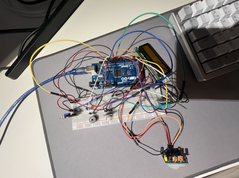
I developed the Arduino-based sensor controller that manages lights, an LCD screen, PIR motion detection, a buzzer, an RGB LED, a photoresistor and a DHT11 temperature and humidity sensor.
The code is written in C++ using the Arduino framework in VSCode and is structured according to object-oriented programming (OOP) best practices. This makes the system modular, more maintainable, and easier to expand in the future.
The controller supports four operating modes:
AUTO: Lights are controlled by a photoresistor – on when dark, off when bright.
ON: Lights remain on at all times.
OFF: Lights remain off at all times.
GUARD: The PIR motion sensor is activated. If motion is detected, the buzzer and RGB LED are triggered. The alarm lasts for five seconds if no further motion is detected; otherwise, it continues.
The LCD display updates to show the current mode and LED status. The Arduino also communicates with the Raspberry Pi via serial commands (AUTO, ON, OFF, GUARD, SENSORMEASUREMENT, LEDSTATUS).
Arduino Sensor Server
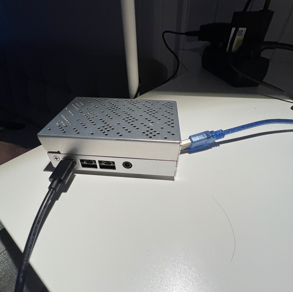
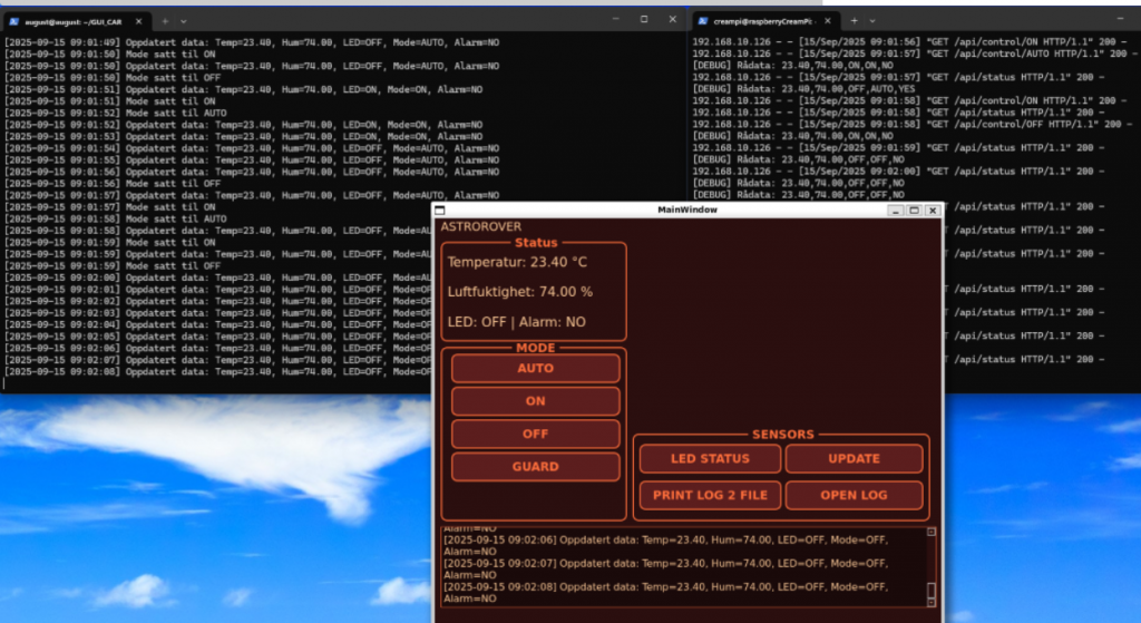
On the Raspberry Pi, I implemented a Flask-based Python server that communicates with the Arduino via serial connection (pyserial). Sensor readings are collected every second and stored in a dictionary for easy access.
The server logic includes:
Updating alarm status if the system is in GUARDIAN mode and the PIR sensor reports motion.
Providing a REST API:
GET /api/status → returns the latest sensor readings and alarm state.
GET /api/control/ → changes the operating mode (AUTO, ON, OFF, GUARDIAN).
This server acts as the central data hub between the Arduino hardware and the GUI application.
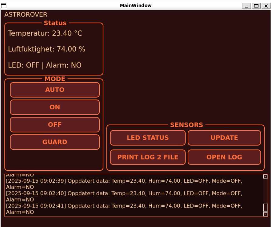
GUI Application
To make the system user-friendly, I developed a GUI in PyQt5. It provides a live display of temperature, humidity, LED status, and alarm status.
Key features include:
Automatic updates every second using QTimer.
Buttons for controlling modes (AUTO, ON, OFF, GUARDIAN).
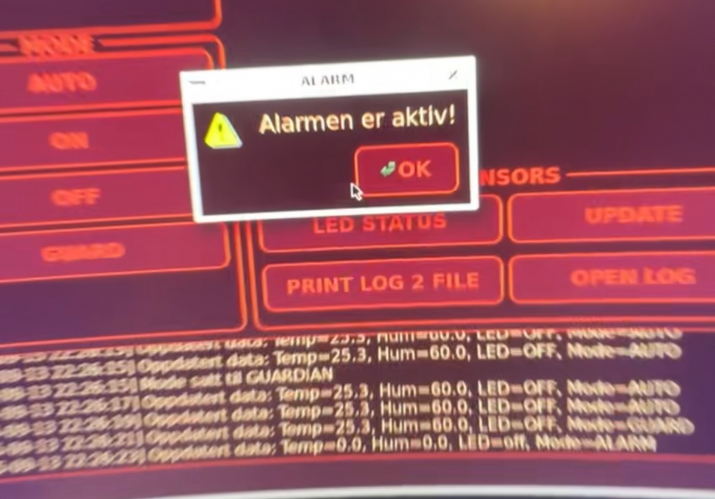
A pop-up warning when the alarm is triggered.
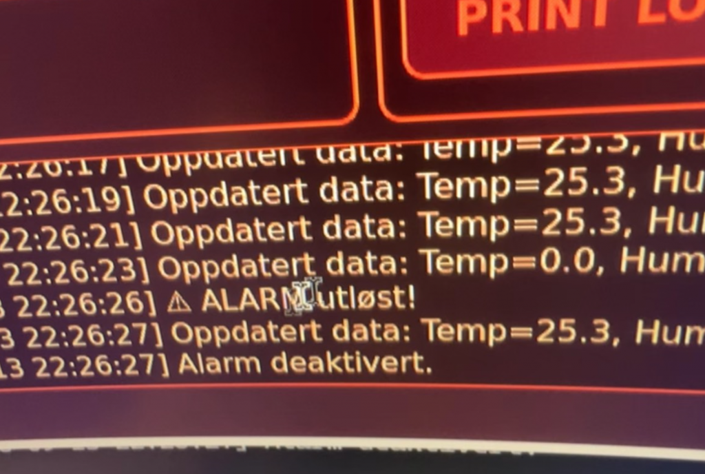
Logging functionality that writes system events and alarms to system_log.txt.
The upper right blank square is ready for video feed. We must implement the camera to the system.
The write to file is a simulator for cloud storage. The plan was to implement clod based storage, but most of them costs money. So this is more a proof of concept. That would be a feature. The alarm pop-up window is also a concept that coul be used on a phone to alert while being locked.
Git / GitHub Workflow
I branched out in the GitHub repository for both the server and GUI code. Work is divided into separate branches (e.g., gui, sensors) to allow parallel development. During this process, I gained experience handling merge conflicts, upstream branch setup, and authentication issues.
Integration
The full system integration works as follows:
Arduino collects and sends sensor data via serial connection.
The Flask server on the Raspberry Pi reads the data and updates the shared data structure.
The GUI queries the Flask server to display real-time information.
User input from the GUI (mode changes) is sent to the Flask server via HTTP requests, which then communicates the new commands to the Arduino.
This ensures smooth, real-time interaction between hardware, server, and interface.
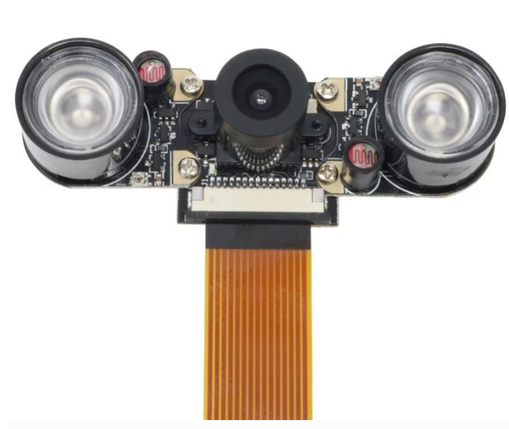
Camera Module Research
I also researched suitable camera modules for the Raspberry Pi and decided on the ZeroCam NightVision. It is fully compatible with the Raspberry Pi 4, includes built-in IR LEDs for night vision, and has an adjustable lens. This module is well-suited for integration with guard mode, where the camera should begin streaming when motion is detected.
Next Steps
In the coming week, I plan to implement the camera module and integrate it with guard mode so that streaming begins automatically upon motion detection. I will also meet with Richard to get further on the car design and begin mounting the Arduino and sensors onto the vehicle.
Sander:
This week I worked on connecting the rover’s motor system with ROS 2 and setting up joystick control using the x56 logitech flight stick. The aim was to have the joystick on my PC send velocity commands all the way down to the microcontroller so the rover could respond in real time.
Joystick on PC
On my Ubuntu machine I set up joy_node and teleop_twist_joy.
joy_node reads raw input from the USB joystick and publishes it on /joy.
teleop_twist_joy maps those inputs into a geometry_msgs/Twist message and publishes on /cmd_vel.
With this, I had a clean ROS 2 interface that converted joystick input into velocity commands.
Networking with the Raspberry Pi
I then configured the Raspberry Pi to join the same ROS 2 domain. This allows it to subscribe directly to /cmd_vel over DDS (CycloneDDS). It replaces my earlier workaround using rosbridge in WSL, and the result is both simpler and more reliable. Most of the debugging went into getting DDS to work with WSL, because of the way WSL handles networking, the pi had difficulties reaching the wsl client.
Motor Driver Node on the Pi
On the Pi I wrote a custom ROS 2 node called motor_driver.
It subscribes to /cmd_vel.
It translates incoming messages into string commands like F-2000, BL-1500, or CCW-1800.
These commands are sent via serial to the micro:bit.
This separation keeps ROS 2 responsible for high-level velocity control, while the micro:bit handles low-level motor driving.
Micro:bit and Motor Control
The micro:bit runs a PlatformIO/Arduino sketch using the Adafruit PCA9685 servo driver.
It parses the serial commands.
It controls the correct wheels for forward, backward, sideways, diagonal, and rotational movement.
A minimum PWM threshold was added to overcome the dead zone where the motors would just buzz instead of turning.
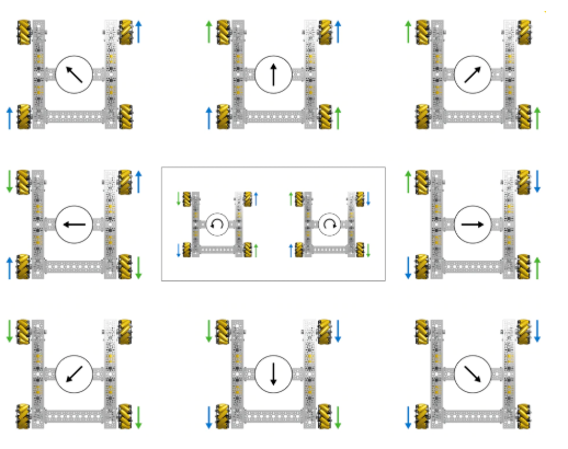
Getting the motor driver code to run correct was a bit of a hassle, but this picture helped with the implementation of the omni wheel maneuvers.
Current Status
Joystick input on the PC produces valid /cmd_vel.
The Raspberry Pi receives the messages and forwards commands to the micro:bit.
The micro:bit parses the commands and drives the motors.
The rover responds correctly to forward, backward, lateral, diagonal, and rotational commands using the flight joystick to control all directions making good use of the rovers omniwheels. Twisting the joystick will turn the rover in its place, moving it to the left will the rover will strafe to the left as well as diagonal movement when moving the joystick forward and to the right etc.
Next Steps
This implementation using ROS2 nodes will simplify the implementation of automatic navigation, by letting the autopilot node publish to the /cmd_vel topic.
Oliver:
LIdar
This week I familiarized myself with the LiDAR we’re going to use. It was missing a strap, so I’ve tried to source a new one and replace it. I’ve tested a few different options, but none have been good enough. I tried using thread, but it didn’t work well; it provided too little resistance for it to rotate properly, and it occasionally got caught on the knot. The next step is to test with a rubber band. I haven’t found the right size yet.
I’ve also been working on getting the LiDAR up and running. It took quite some time to make it send data to the Arduino and to get the Arduino to read data from the LiDAR. I therefore had to do quite a bit of troubleshooting before I was able to read data.
To check whether we were receiving any data at all, I found that it didn’t work on the pin I was using. I tested two different pins and was able to get 2D data and distance. I’ll troubleshoot why it doesn’t work on UART 18/19 to achieve better distance measurements.
I was able to read distance using pin 2, but it wasn’t accurate, so it needs to be calibrated. It showed a very large error compared to the distance it was supposed to measure.
The next step is to get the strap working and switch over to pins 18/19 to use UART. Then I’ll calibrate the LiDAR so it shows the correct distance.
Sondre:
Camera Module
This week I worked with the camera module and experimented with it. I started by using it with Pi OS since it is just “plug and play” to check how it works in practice. Later I tried to get it running on Ubuntu 22.04, which was more challenging because it lacks the necessary packages.
I therefore had to test several different solutions, including libcamera and GStreamer, but encountered multiple issues along the way with missing drivers and compatibility. However, this gave me a better understanding of how the camera actually communicates with the system, and which layers of the software need to be in place for it to work.
The next step will be to get the connection between the camera and Ubuntu fully working, and then integrate this feed into ROS2 so we can use it in our project and combine the camera data with the other sensors we plan to connect.